Project Name :- Control the position of servo motor using the potentiometer
Today i am going to show the control of the direction of the servo motor on varying the value of the potentiometer.
Component required
- Computer
- Arduino UNO with cable
- Servo motor
- 10 kohms potentiometer
- Jumper wires
And a software named Arduino IDE in computer also we need library file for servo .
According to Wikipedia "A servo motor is a rotary actuator or linear actuator that allows for precise control of angular or linear position,Velocity and acceleration.It consists of a suitable motor coupled to a sensor for position feedback."
Differ from the other motor,Servo motor have three wires ground,power and the signal.The brown color indicate ground,red wire indicate positive supply of the arduino. and the last is orange color which indicate the signal.
fig :- servo connector
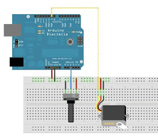
We are going to control the direction of the servo motor via potentiometer,arrange the circuit as shown below
fig:- circuit arrangement
code
#include <Servo.h>
Servo deneshservo; //create object to control the servo
int potpin=A0; // connect analog pin of potentiometer
void setup() {
deneshservo.attach(9);//attach the servo signal pin on pin 9 of arduino
}
void loop() {
int val = analogRead(potpin); //read the value of potentiometer between 0 to 1023
val=map(val,0,1023,0,180);//scale the value of potentiometer to 0 to 180 to use in servo
deneshservo.write(val); //set the servo according to the scaled value
delay(15); //delayed time
}
In this project we,first measure the value of the potentiometer the we scale it using map function from 0 to 180.And we set the servo according to the scaled value.

