This program focuses on designing a C# app to connect to a PLC and read/write the switch bits of the PLC. It serves as a sample project demonstrating the use of a Mitsubishi PLC Q03UDV and MX Component 4 for setting up communication, along with Gx Works2 for designing a simple ladder program for the PLC. Click here to know introduction to PLC,its symbols
Objective
- To Design .NET program that Read/Write the bit of switch of PLC.
Used Hardware
- Mitsubishi PLC Q03UDV
- PC
- Router
- LAN cables
Software used
- Visual Studio
- Mx Component
- Gx Works2
The project is classified into 3 parts
- PLC side setup.
- Mx component setup.
- C# application.
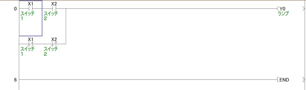
PLC side setup
We utilized Gx Works2 to create a simple ladder program for controlling a lamp using a double switch. You can create your own program and configure the communication settings to upload the program to the PLC.
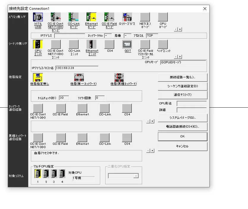
To set up communication between the PLC and PC based on our requirements, we selected Ethernet communication, as illustrated in the figure below.
Mx component Setup
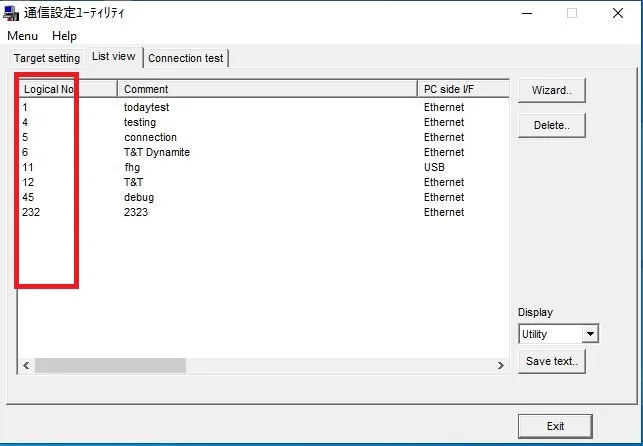
Mx Component is a powerful tool that enables programmers to easily connect Mitsubishi PLCs with Microsoft PC software. By utilizing the Communication Setup Utility, setting up and testing the communication becomes a straightforward process. For detailed information, please refer to the MANUALS
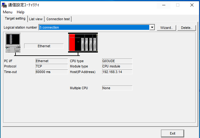
Configure communication parameters such as communication mode, timeout settings, and error handling to ensure reliable communication between the PC and the PLC.Use the provided testing tools or utilities within MX Component to verify the connection between the PC and the PLC. Test reading and writing bits to ensure the setup is functioning correctly.Save the communication configuration settings for future use. It’s essential to have a backup of these settings for easy reconfiguration or troubleshooting. Always use a unique Logical Station Number during the setup. This number will be used to connect the PLC with the .NET program.
Design the .Net Program
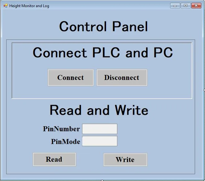
Here, we design an interface with four buttons: ‘Connect,’ ‘Disconnect,’ ‘Read,’ and ‘Write.’ These buttons facilitate setting up the connection and performing read/write operations on the PLC switch bits.
- Connect Button:- The ‘Connect’ button is utilized to establish a connection between the PLC and the C# application. It verifies the Logical Station Number set in the Mx Component, if it matches the defined value in the Mx Component, successful communication between the PLC and the C# application is established.
- Disconnect Button:- If a connection was successfully established between the PLC and the C# program, clicking the ‘Disconnect’ button will terminate the connection with the PLC.
- Read Button:-If a connection is established between the PLC and the C# application, and a bit of the switch’s name is entered into a pin number textbox, upon clicking the ‘Read’ button, the state of the switch will be displayed in PinMode textbox.
- Write Button:- Similar to the ‘Read’ button, upon clicking the ‘Write’ button, it will write the state of the switch whose name is entered in the textbox.
Click here to access the source code for this functionality
You can check our official site Samkartech for more tech related project