
This article is the simple integration between Arduino and c# applications,Unlocing a realm of possibilities for automation. Here we'll explore a practical approach to PDF automation using Arduino inputs and C# interfacing.
Introduction
Automating processes related to PDF files can significantly enhance productivity and streamline workflows. By combining the flexibility of Arduino sensors with the robust capabilities of C# applications, we can create a system where physical inputs trigger actions in a digital environment.
Used Softwares
Used Hardware
- Arduino
- Switches
- LED(in place of sensors)
- jumper wires
Setting up Environment
Arduino side

It involves the utilization of two switches to independently control two Light Emitting Diodes (LEDs). Serial communication is established through the command Serial.begin(9600). When LED1 is activated, a corresponding message, "Switch 1 is on!" is transmitted through the serial communication. Similarly, when LED2 is illuminated, a corresponding message, "Switch 2 is on," is sent.
Program for LED Control and Message Transmission in Arduino via Serial Port
  int switch1State = digitalRead(switch1Pin);
  int switch2State = digitalRead(switch2Pin);

  // Control LED 1
  if (switch1State == LOW) {
    digitalWrite(led1Pin, HIGH);
    Serial.println("Switch 1 is ON!");
  } else {
    digitalWrite(led1Pin, LOW);
  }

  // Control LED 2
  if (switch2State == LOW) {
    digitalWrite(led2Pin, HIGH);
    Serial.println("Switch 2 is ON!");
  } else {
    digitalWrite(led2Pin, LOW);
  }

  // Add a small delay to debounce the switches
  delay(50);
Visual studio side
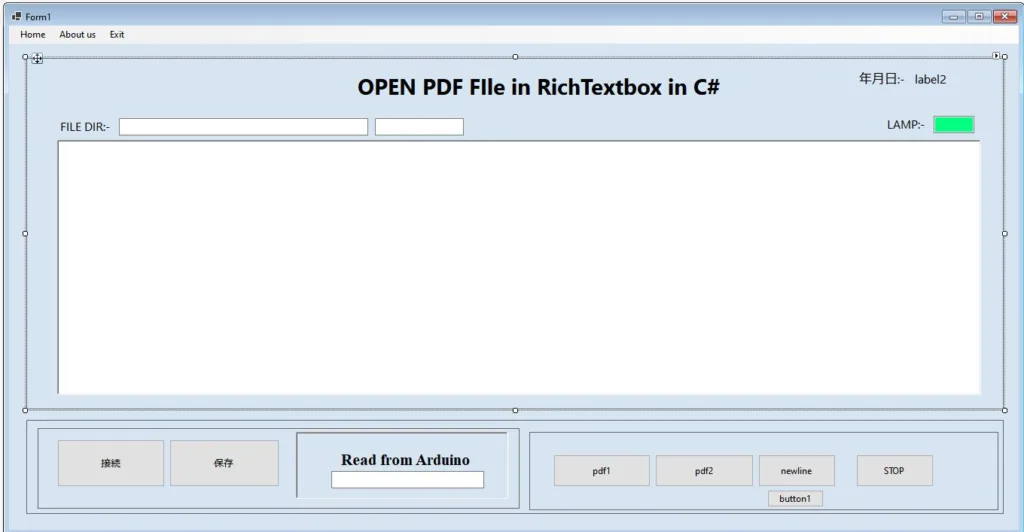
Here in Visual Studio, the Windows application is programmed in such a way that when the connection button is clicked, it checks if the port is available. If the port is available, it reads the serial port and displays the message in TextBox 3. If the message is "Switch 1 is on!", it then turns on PDF1 from the local directory in the RichTextBox and adds a comment to it. The same process is applied to LED2.
Program in C# to set up serial communication with Arduino.
 private void connection_Click(object sender, EventArgs e)
 {
     try
     {
         if (!serialPort.IsOpen)
         {
             serialPort.Open();
             MessageBox.Show("sucessfully connected");
             int delayMilliseconds = 50;
             Thread.Sleep(delayMilliseconds);

             timer = new System.Windows.Forms.Timer();
             timer.Interval = 50; // Set the interval to 100 milliseconds
             timer.Tick += Timer_Tick;
             timer.Start();
         }
         else
         {
             serialPort.Close();
             MessageBox.Show("serial port close");
         }
     }
     catch (Exception ex)
     {
         MessageBox.Show($"Error: {ex.Message}", "Error", MessageBoxButtons.OK, MessageBoxIcon.Error);
     }


 }
Testing
Source code clickhere
Also Read C# App to Read/Write Switch PLC Bits: A Comprehensive Guide
future advancement
This program serves as a small-scale testing section. In the future, it will be integrated into a conveyor system that features various inspection stations. If an error is detected at any station, the program will promptly display the corresponding PDF file, automatically read the error, and illuminate the error lamp.
conclusion
In conclusion, the development and implementation of this program mark a significant step forward in enhancing efficiency within conveyor systems. The small testing section lays the groundwork for seamless integration into a larger framework featuring multiple inspection stations. This system not only identifies errors promptly but also streamlines the troubleshooting process by displaying relevant PDF files, automatically reading errors, and activating the error lamp. With its advanced capabilities, the program promises to contribute to a more robust and responsive conveyor system, ultimately optimizing overall operations and minimizing downtime.
For details https://samkartech.com/